


Measurement Units
- Two measurement devices used in A.R.I.S.E. system
- Load cell is used to measure the weight of riders
- Accelerometer is used to detect when the ride is in motion and the speed of the ride
Load Cell

- Strain Gauges are mounted on the part of the device that will bend the most
 |
- Change in length of Resistance affects Voltage
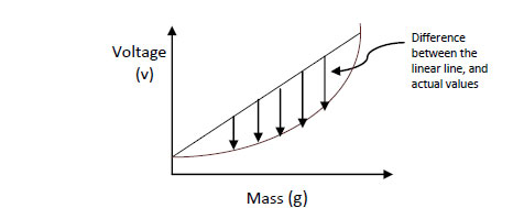
- The measured voltage of the strain gauge is proportional to the mass bending the beam however it is not linear

- Bridge circuit is developed due to the very small changes in resistance that needs the be measured
- This configuration allows it be less affected by the changes in temperature

- To amplify the small signal, an Instrumentation Amplifier (AD620AN) is used

- Diode configuration is used to limit the input voltage of the micro-controller

- Zeroing circuit is used to calibrate the Load Cell

- Two load cell devices will be placed at both ends of the seat to detect the weight of each rider

- This is the algorithm that is used to detect when a rider is not properly seated
- large safety margin is used to compensate for the rider's body shifting during the ride operation
- Once warning has triggered, it will remain on until the person has returned to their seat or the ride has come to a complete stop
Implementing The Load Cell
- AD1PCFG is a mask used to determine which pins will be configured as analog or digital (0=digital, 1= analog)
- AD1CON1 is a register that sets the conversion start automatically
- AD1CSSL determines if a scanning function is required
- AD1CON2 uses MUXA and connects the AVdd and AVss pins to the ADC reference inputs
- AD1CON3 is a register that is used to configure the clock
Steps to setting up the ADC Controller
- Select the Input Channel (AD1CHS)
- Start the sampling and the conversion (AD1CON1bits.SAMP)
- Wait for the conversion to complete
- read the value from the buffer (ADC1BUF0)
Accelerometer

- Accelerometer used is the MEMSIC 2125 dual axis accelerometer
- capable of measuring the force along the x and y axis
- allows tilt angle, g force, and speed to be measured by manipulating the data and performing calculations
- Accelerometer produces a pulse width modulated signal which is read by detecting the rising and falling edges of the signal
- Two interrupt service routines are required to measure on both x and y axis
- The time between the rising edges is the period and the time between the rising and falling edge is the duty cycle
- The duty cycle is used to determine the amount for that is experienced by the accelerometer
- The ride speed is determined by measuring the time difference between two peaks in G force
- On a hypocycloid type ride this will be equal to one rotation


